Configure Print Settings
Parameters in the Print Tab allow you to adjust various parameters for your print job. Let's walk through each of them:
Layers
-
Layer Height: Adjust the height of each printed layer, thinner layers result in finer details but take longer to print,
0.05mmis a typical value that provides a good balance between detail and print speed. -
Bottom Layer Count: This sets the number of solid layers at the bottom of the print, which helps with adhesion to the build plate. A common value is
4, but you can adjust it based on your specific print requirements.
Exposure Time
- Exposure Time/Bottom Exposure Time: This controls the duration that each layer is exposed to the light source. Longer exposure times can improve layer adhesion but may also lead to overexposure and loss of detail. There are many factors that can affect your exposure settings, the recommended exposure time given by resin manufacturers or printer manufacturers might not be suitable for your specific print job, but it can be a good starting point for adjustments. We recommend walk through the Printing Test Guide to find out the exposure time for your specific print job.
Transition Layers
-
Transition Layer Count: This sets the number of layers that transition from the bottom exposure time to the normal exposure time. This is useful for prints with an extra long bottom layer exposure time, as it helps to gradually transition to the normal exposure time, reducing the risk of cracking between the bottom layers and the regular layer.
- Transition Type: the algorithm used to transition between exposure times. Currently only
Lineartransition is supported, it gradually changes the exposure time over the specified transition layer count. For example, if you set the transition layer count to4, it separates the transition interval into 5 equal parts, for regular exposure time of2.5sand bottom exposure time of25s, the exposure time for each transition layer will be20.5s,16s,11.5s, and7s. - Transition Layer Interval Time Difference: this indicates the time difference between each transition layer, it's calculated automatically and is not editable. In our example, the transition layer interval time difference would be
4.5s((25 - 2.5)/5 = 4.5).
- Transition Type: the algorithm used to transition between exposure times. Currently only
Waiting Mode
-
Waiting Mode During Printing: This selects the waiting mode during printing, it determines how the printer behaves between layers. Supported modes are
Resting timeandLight off delay.-
Resting Time: this mode allows you to set up specific waiting time before lift, after lift, and after retract, where
Rest Time After Retractcan be relatively critical, sufficient waiting time ensure the resin goes back to a static state after retraction, and ready for the next layer exposure. -
Light Off Delay/Bottom Light Off Delay (legacy): Light-off delay is the total time of build plate lifts up, wait, and retract.
WARNINGThe Light off delay mode is a legacy option, we recommend using the Resting Time mode for better control over the printing process. Some 3rd-party printers (doesn't use the .ctb format) may use the same option name but doesn't strictly consist of our definition here, we recommend reaching out to the printer manufacturer for details, or try it out yourself before printing.
-
Distance and Speed
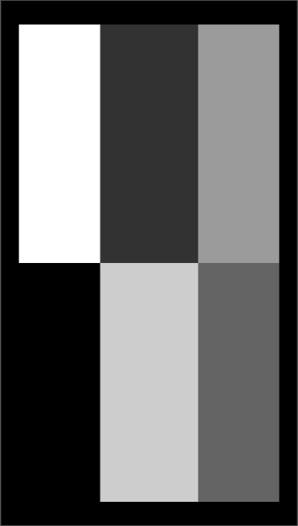
Both distance and speed are separated into settings for bottom layers and regular layers. Each of these is then further divided into parameters for lift and retract, which can each be separated into two phases for better flexibility. Note that the order of the fields is important, the diagram located below the parameters highlights each phase when a specific input field is focused, please make sure you don't input values in the wrong field.
-
Lift Distance/Bottom Lift Distance: This sets the distance the build plate lifts after each layer is printed.
-
Retract Distance/Bottom Retract Distance: This sets the distance the build plate retracts after each layer is printed.
NOTERetract distance is limited by the Lift Distance, it's sum must equal the corresponding Lift Distance, therefore you can only modify one field of Retract Distance, CHITUBOX will calculate the other field automatically.
-
Lift Speed/Bottom Lift Speed: This sets the speed at which the build plate lifts after each layer is printed.
-
Retract Speed/Bottom Retract Speed: This sets the speed at which the build plate retracts after each layer is printed.
Advance
Advanced settings provide additional control over the printing process, allowing for fine-tuning to achieve optimal print quality.
Light PWM
PWM is short for Pulse Width Modulation. The principle is to control the light intensity of the light source by adjusting the duty cycle of the light source per unit time.
Light PWM and Bottom Light PWM control printers' light intensity for normal layers and bottom layers respectively. You can adjust the parameters based on your own cases.
Picture Grayscale
Picture Grayscale controls the grayscale of the exposed area of the slice image (without supports). Ranging from 0 to 255, the value is connected with the pixels' color: higher value means pixels are closer to white, and lower value means they are closer to black.
For LCD printers, the whiter the exposed area of the slice image, the higher the light transmittance. For DLP printers, the whiter the slice image's exposure area, the greater the light intensity.

Anti-aliasing
Anti-aliasing has two modes: Gray Scale Level and Anti-aliasing Level.
- Gray Scale Level:
Gray Scale Level reduces triangular sawtooth by greyscale feathering the edges of the sliced image for LCD printers. The minimum and maximum values of grayscale are adjusted by moving the two sliders or directly inputting numbers (between 0 and 255). Pixels generated for anti-aliasing will fall into this greyscale range. The larger the value is, the whiter the pixels are, leading to higher transmittance and cured degree.
The Gray Scale Level bar works together with the Image Blur Enable option. When Image Blur is enabled, the gray scale level will be applied with a blur effect to further smooth the edges. Image Blur Pixel ranges from 2 to 8. The higher level you select, the softer the edges are, but the image may become less sharp and lose detail.
- Anti-aliasing Level (legacy):
This option has been retained only for a few legacy DLP printers. The format is already deprecated and is not compatible with newer DLP printers.
Shrinkage Compensation
Shrinkage Compensation is in principle no different from scaling a model. It works on the current configuration rather than a particular model, avoiding the need to manually modify the model size when switching between different printers or configurations.
Shrinkage Compensate uses a percentage to scale from the original size with the default at 100%. The model body turns larger with a larger percentage value, and smaller with a smaller percentage value.
Tolerance Compensation
Tolerance Compensation and Bottom Tolerance Compensation control compensation for printers' normal layers and bottom layers respectively, typically used to resolve the fit of workpieces such as bolts and nuts, mortise and tenon construction. Bottom Tolerance Compensation is usually used to resolve the "elephant trunk" effect due to long exposure time.
Tolerance compensation works by labeling the inner diameter (a) and outer diameter (b) of each layer of the exposed image, and then adjusting the size of the inner and outer diameters according to the tolerance compensation values.
When a is larger, the inner diameter is shorter. When a is smaller, the inner diameter is longer.
When b is larger, the outer diameter is longer. When b is smaller, the outer diameter is shorter.
- When the bottom layer tolerance compensation is disabled, the normal layer tolerance compensation will be effective for the whole model.
- Tolerance compensation works by check the inner diameter (a) and outer diameter (b) of each layer, not by scaling 3D models directly. As a result your models should not have sudden changes in inner and outer diameters (i.e. inner diameter changes to outer diameter or vice versa at a certain height). For example, such changes to a slice file may happen for a vertical tube with an horizontal hole at a certain height.
- Bottom tolerance compensates only affects bottom layers. When transition layer compensation and bottom tolerance compensation are both enabled, the print result may be not be as good as expected.
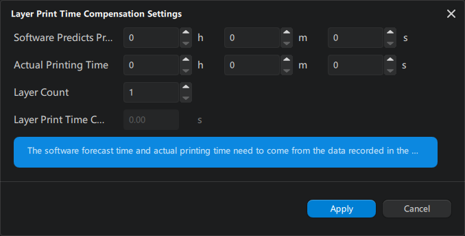
Print Time Compensation
Some high-resolution printers can have extra delays when loading data and will lead to inaccurate printing time estimation. You can set up a time compensation to improve the issue.
-
Manual Input
Layer Print Time Compensation: a 2-digit number between
-99.99and99.99with default set at0s.When enabled, the Estimated Time For A Single Layer = Exposure Time + Waiting Time + Movement Time + Layer Print Time Compensation
-
Auto Generation
Mask
Mask is designed to solve a common light source issue of uneven light strength at different spots of the screen. The issue is usually caused by improper light sources. The purpose of the mask is to provide a correction layer on the screen by adjusting the transmittance on different areas of the screen respectively, making the uneven light homogeneous.
Mask File: You can select an existing image by clicking the ... icon, or click the gear icon to create a new one using CHITUBOX's built-in mask generator.
-
Mask Generator
Mask Generator in CHITUBOX supports two modes: Hub-and-Spoke and Matrix Mode。
-
Hub-and-Spoke
Hub-and-Spoke generate a ripple-like pattern. The number of circles is set by Number of equal parts. Radius of circles are arithmetic sequence with a delta set by Equal radius.
The range of Gray Parameter is between
0(black) to255(white)。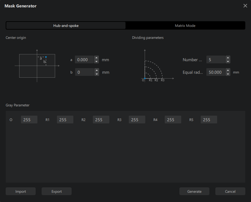
For example, if Number of equal parts is set to 5, Equal radius is set to 3mm, the radius of the ripple will be
Here is a comparison for different Equal radius:
Number of equal parts set to 5, Equal radius set to 1mmNumber of equal parts set to 5, Equal radius set to 3mm -
Matrix Mode
Matrix Mode generates a matrix-like pattern. Rows and columns are set by
mandnrespectively. The range of Gray Parameter is from0(black) to255(white)。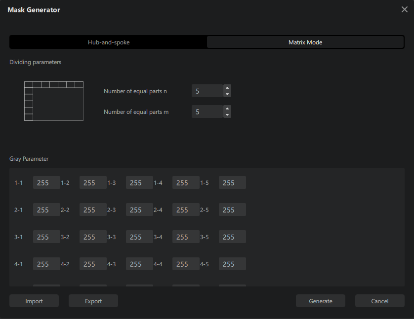
Here is a 2 × 3 matrix with different grayscales.
-
-
Gray scale unit
Gray scale unit is used to average the gray value of specified number of pixels in X-axis direction, and apply averaged grayscale to pixels in corresponding position of the original image.
Example:
Let's say the size of the build plate is 80mm × 120mm, the resolution of the screen is 800px × 1200px.
Below we have the mask picture on the left side with the same resolution of 800px × 1200px. Inside it are 384 small squares of size 50 × 50 pixels.
If the Gray scale unit was set to 51px, the mask image will look like the picture on the right side above.
The grayscale increases from left to right as a result of averaging out every 51 pixels. Take the first row as an example: The first 51 pixels include 50 black pixels and 1 white pixel. The resulting average value is a tint lighter than pure black, barely noticeable to the naked eyes. The second group of 51 pixels contains 49 white pixels and 2 black pixels, averaging out to a color slightly darker than white. The third group of 51 pixels will be masked to the average grayscale of 48 dark pixels and 3 white pixels and so on, until we reach the remaining 35 odd pixels.
, remainder 35
This remaining pixels' gray scale will be the average of 35 pixels of the same shade. Therefore, the resulting grayscale doesn't change.
Save Settings
The Apply to Project button applies the configuration you selected in the Configuration List to the current project.
While the Save button saves your changes to the currently selected configuration.