Configure Support Parameters
This page describes Support Settings, click here to learn more about support placement and editing.
To open Support Configuration Panel, you need to navigate to the Support tab first.
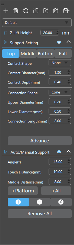
This is the Support Configuration panel, where you can add

, delete

, reset

, import

, export

, export all

, save

, and rename your support profiles. Profiles can be manually saved or maintained with auto-saving.
Z Lift Height: The vertical offset between the lowest point of the model and the platform.
Support Settings
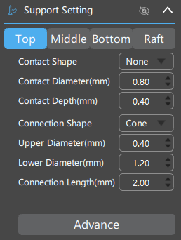
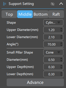
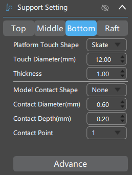
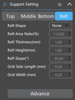
You can edit Top, Middle, and Bottom of your supports respectively.
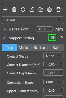
Visualized editing panel is also provided for better user experience, where you can modify support parameters directly on the 2D diagram. You can also turn it off by clicking the

button on the Support Settings panel.
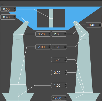
Visualized editing panel
Top
Middle
Bottom
Raft
Advanced
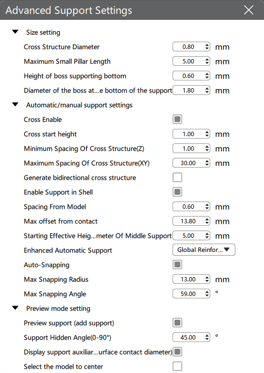
The Advanced Settings button leads to a new dialog providing more detailed settings for support dimensions and placement.
Starting from CHITUBOX Basic v1.8.1, by default we disabled support auxiliary lines calculation when loading models to reduce loading time and improve user experience. Auto support will calculate auxiliary lines with the option turned on (the auxillary lines would only show on critical areas, different than in Basic V1.8.1, with the manual removal of auto-generated supports). We recommend using the red hightlight as a reference to high-risk areas instead.
| Parameter Group | Parameter | Explanation |
|---|---|---|
| Size setting | Cross Structure Diameter | Diameter of bracing structures between main support columns.  |
| Maximum Small Pillar Length | Maximum length of small pillars. Supports with both ends contacting model surfaces would be sized at Diameter of Small Pillar, when the total length of the supports do not exceed Maximum Small Pillar Length. Otherwise the size of the supports would be based on Upper Diameter of the Top segment.  | |
| Height of boss supporting bottom | Height of the bottom cone structure connecting the support base to the main supporting column.  | |
| Diameter of the boss at the bottom of the support | Diameter of the bottom cone structure connecting the support base to the main supporting column.  | |
| Automatic/manual support settings | Cross Enable | Enable/Disable cross bracing between main supports.  |
| Cross start height | Set cross bracings' minimum offset from the printing platform. Cross bracings would only generate on supports with total heights larger than the value of this parameter.  | |
| Minimum Spacing Of Cross Structure(Z) | Set the minimum vertical offset between two cross bracings.  | |
| Maximum Spacing Of Cross Structure(XY) | Set the maximum lateral offsets between supports for cross bracing generation.  | |
| Generate Bidirectional Cross Structure | When manually adding supports, cross structures are automatically generated between the new support and its adjacent supports on both sides. | |
| Enable Support in Shell | Enable/Disable interior support generation for closed-chamber structures when applying auto-supporting.  | |
| Spacing From Model | The minimum lateral offset allowed between the main column of a support to any point on the model surface.  | |
| Max offset from contact | The maximum lateral offset allowed between a support's model contact point and its main column's centerline. Supports rooted on the print platform would only generate when the lateral offset is within limit set by this parameter during manual support placement.  | |
Starting Effective Height Of Lower End Diameter Of Middle Support | Minimum support height for the Lower End Diameter of Middle Support parameter to set the size of the support's main column. The support's main column will be sized at the Upper End Diameter if the height of the support is less than this value.  | |
| Enhanced Automatic Support | Enable/Disable Enhanced Automatic Support.  | |
| Small Column Automatically Absorbs | Enable/Disable automatic attachment of small columns.  | |
| Preview mode setting | Preview support (add support) | Enable/Disable preview when adding supports manually.  |
| Support Hidden Angle(0-90°) | In the support mode, the middle and bottom segements of supports will be hidden automatically when the viewing angle exceeds this value. Set the parameter to 0 to maintain visibility at all view angles.  | |
| Display/Hide support auxiliary lines, showing the contact points for auto-supports. | Display/Hide support auxiliary lines, showing the contact points for auto-supports.  | |
| Select the model to center | The selected model is automatically placed at the center of the view in Support Mode.  |
Enhanced Automatic Support
Auxillary supports with cross bracings will be added automatically to certain isolated supporting columns during Auto Support.
-
Triangular Reinforcement (TR): The program will try to automatically connect adjacent support columns to form stable triangular structures with Trianglular Reinforcement during Auto Support.
-
Global Reinforcement (GR): The program will try to inter-connect all adjacent support columns to form a more stable structure composed of small triangular structures under Global Reinforcement during Auto Support.
Enable automatic adsorption of small columns: You can freely set the size of the adsorption radius. The software will automatically attach the lower end of the small column to the appropriate support when adding the small column support according to the algorithm.
Auto/Manual Support
Angle (°): The maximum tilt angle of model surface allowed for auto support. The angle is calculated as the angle between the surface and the print platform.
Touch Tip Distance (mm): The minimum horizontal distance allowed between any two support tips contacting the model surface.
Middle Distance (mm): The minimum lateral distance between any two supports' main columns.
The Density(%) parameter used by CHITUBOX Basic was replaced with the Middle Distance(mm) in CHITUBOX Pro to achieve more accurate support spacing settings.
This button automatically adds supports based on platform only.
This button automatically adds supports originated from the platform and between model geometries when necessary.