UI Introduction

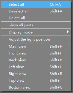
Right-clicking the blank area will bring up the Viewport menu
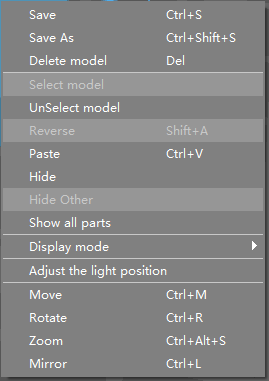
Right-clicking on models will bring up the model menu
There is also a tiny white triangle button on the right-bottom corner of the Viewport that provides a list of frequently-used global and local shortcuts.


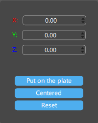
Move: move the selected models to the set position.
-
Put on the plate: set the selected model on the build plate using the lowest point of the model as the reference point.
-
Centered: center the selected model on the printing platform.
-
Reset: reset the placement position of the selected model.
Rotate: rotate the selected models according to the set angles.

-
Flatten by face: set the model against the printing platform by aligning the selected surface to the platform.
-
Combination center: take the center of the selected combination of multiple models as the center of rotation.
Scale: scale the selected models based on set dimension or scale percentage.

-
Lock ratio: lock the ratio of the selected model's X-axis, Y-axis and Z-axis for scaling.
-
Support diameter unchanged: scale supports with the model while keeping support columns' diameter unchanged.
-
Scale to fit: scale the selected model to fit the printing platform.
-
Reset: reset the model size.
Mirror: mirror the selected models.
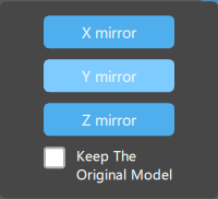
- Keep the original model: if this option is enabled, the original model will be retained after mirroring.
Title Bar provides quick access to open file, save file, undo, redo, login and screenshot/screen recording.
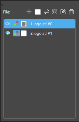
This panel allow you to add files, select/unselect (all) files, reverse select files, auto/manually color objects, display/hide printing size, delete files, and display/hide files.
This slider allows you to preview the vertical cross-sections of your objects. Whereas X and Y sliders allow you to preview the horizontal cross-sections of your objects.


For all Axes: red is the X-axis; green is the Y-axis; blue is the Z-axis.
Right-click and drag the blank area to adjust the viewing angle of the work area.
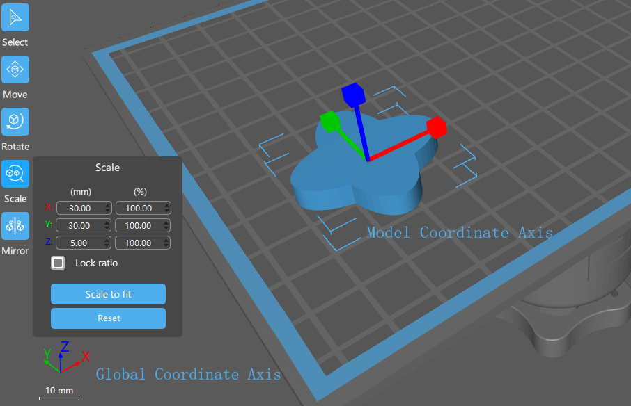
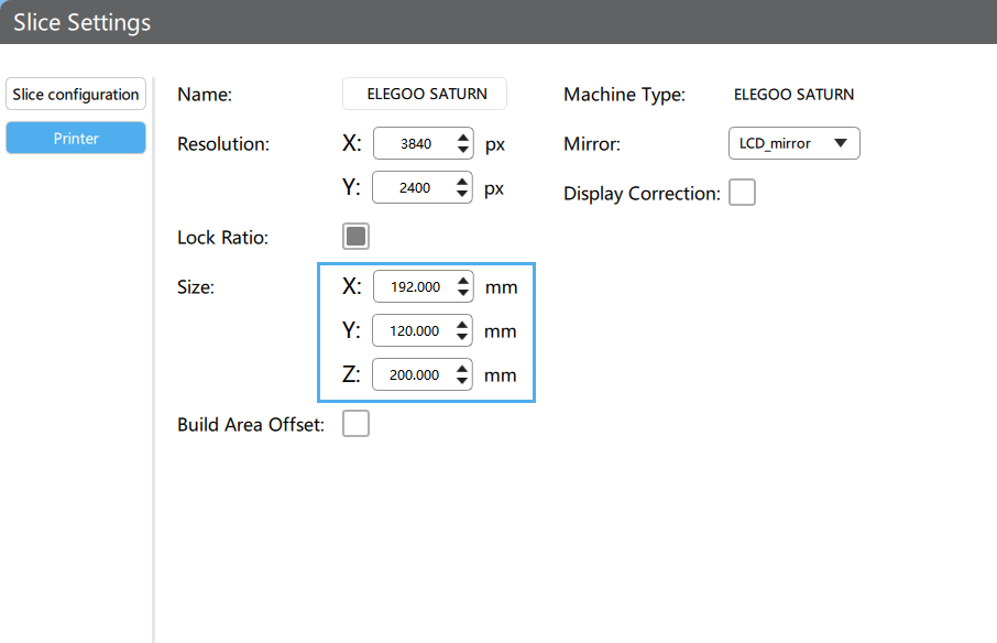
As shown below, the X/Y/Z in the slice setting correpond to the print platform's coordinate axes (Global Coordinate, displayed in the bottom left of the screen). They are used to adjust the maximum print size in the directions of the X, Y, and Z-axis on the printing platform (For built-in printers, please use the default size. for those other printers, please fill in dimension parameters strictly according to the specifications provided by the printer manufacturer).
The dimensions of the model displayed in the zoom panel are the dimensions corresponding to the model's coordinate axes (Local Coordinate), not the dimensions corresponding to the platform's coordinate axes (Global Coordinate). The local coordinate system rotates with the model, not affecting the dimensions displayed in the zoom panel.