Support Configuration
Raft Settings
Model Lift Height
The height distance between the lowest point on the model and the print platform.
Raft Shape
Plate
Cross Grid
Hexagonal Grid
Linear Connection
Support Settings
Support Profile
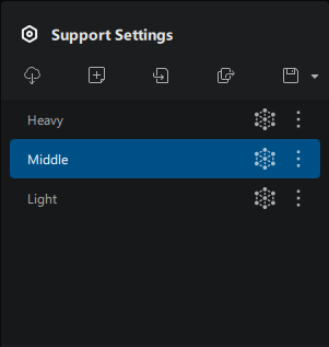
You can Add, Import, Export, and Save support profiles here.
Click the icon to directly open the settings dialog and navigate to "Enhance Auto Support". Hovering over the icon following each profile brings up available actions, including Rename, Export, Reset, and Delete.
Basic Settings
Top Segment Upper Diameter
Diameter at the upper end of the support's top segment.
Angle
Maximum allowable angle between the model surface (tangential plane) and the platform for auto support generation.
Contact Point Spacing
Spacing between each support tip contacting the model.
Main Pillar Spacing
The minimum horizontal distance between any two supports' mid segments.
Contact Point Spacing and Main Pillar Spacing are two important parameters affecting support density. The smaller the values are, the denser the supports.
Advanced Settings
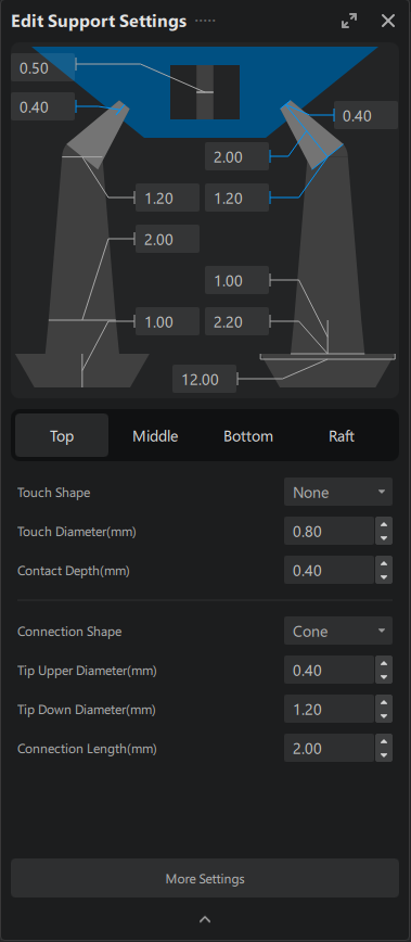
Top
- Top Segment Tip
| Parameters | Description | Image |
|---|---|---|
| Contact Shape | The shape of the support segment contacting the model | N/A |
| Contact Diameter | The size of the support segment contacting the model |  |
| Contact Depth | Depth of the support tip reaching into the model |  |
- Main Top Segment
| Parameters | Description | Image |
|---|---|---|
| Connection Shape | Connection shape of the main top segment |  |
| Top Segment Upper Diameter | The upper end diameter for the support's main top segment |  |
| Top Segment Lower Diameter | The lower end diameter for the support's main top segment |  |
| Segment Length | Length for the main top segment |  |
Middle
- Basics
| Parameters | Description | Image |
|---|---|---|
| Shape | Shape of the main support pillar |  |
| Upper Diameter | Upper end diameter of the main support pillar | N/A |
| Lower Diameter | Lower end diameter of the main support pillar |  |
| Angle | Maximum angle between the middle main support pillar and the top segment | N/A |
- Smaller Pillar
Small Pillar is a type of support structure used to support small spaces, with both ends connecting to model surfaces.
| Parameters | Description | Image |
|---|---|---|
| Small Pillar Shape | Shape of small pillar contacting the model |  |
| Diameter | Diameter of the small pillar |  |
| Upper Depth | Depth of small pillar's upper end reaching into the model |  |
| Lower Depth | Depth of small pillar's lower end reaching into the model |  |
Bottom
Support Bottom includes settings for segments rested on the print platform and settings when the bottom segment rests on the model surface.
- Support segment on the platform
| Parameters | Description | Example |
|---|---|---|
| Platform Contact Shape | Shape of the support bottom segment contacting the platform |  |
| Contact Diameter | Diameter of the support bottom segment contacting the platform |  |
| Thickness | Thickness of the support bottom segment contacting the platform |  |
- Bottom segment on model surfaces
Below options applies to bottom segments rested on model surfaces, in other words, when both ends of a supports contact model surfaces. These settings are no applicable during "Edit" model. Switch to "Add" model to edit the settings.
Raft
| Parameters | Description | Example |
|---|---|---|
| Shape | Shape of rafts |  |
| Raft Area Ratio (%) | Controls the size of the supporting raft, by setting the ratio of the total area of the raft relative to the total area projected by the model to the printing platform |  |
| Raft Thickness | Wall thickness of the supporting raft |  |
| Raft Height | Overall height of the supporting raft |  |
| Raft Slope(°) | Angle between raft's side wall and the printing platform |  |
| Grid Opening Width | Width of each grid opening for grid type supporting raft | N/A |
| Grid Spacing | Spacing between two adjacent grid openings for grid type supporting raft | N/A |
More Support Settings
Entry | |
|---|---|
| Support Settings Panel | Support Settings > Advanced Settings > More Settings |
Enhanced Automatic Support
Auxillary supports with cross bracings will be added automatically to certain isolated supporting columns during Auto Support.
-
Triangular Reinforcement (TR): The program will try to automatically connect adjacent support columns to form stable triangular structures with Trianglular Reinforcement during Auto Support.
-
Global Reinforcement (GR): The program will try to inter-connect all adjacent support columns to form a more stable structure composed of small triangular structures under Global Reinforcement during Auto Support.
Auto Support
Auto Support Mode
Entry | |
|---|---|
| Shortcut | Ctrl + TAB |
There are three modes for auto support: +All, +Platform and +Overhang.
+All allows support generation on model surface, +Platform allows support generation on the platform, and +Overhang generates support on all overhangs.
Auto Support Type
Auto Support type includes: Branch, Joint, Adaptive, Vertical, Upright and Small Pillar.
Choose applicable options from the support types, click the "Auto Add Support" button to generate corresponding support types.