Printer Configuration
One printer can store multiple slicing configuration profiles. Printer configuration consists of four parts: "Machine", "Resin", "Print" and "Advanced".
"Machine" settings are universal and can be applied to all print configurations under the current printer. "Resin", "Print" and "Advanced" settings are independent and can be edited separately for each configuration.
Entry | |
|---|---|
| Profile List | Double Click a Configuration File |
| Slice Panel | Slice Settings |
Machine
Name
Machine Name is a custom name for the printer configuration and can use any characters.
Machine Type
Machine type is the make and model of your printer. Each machine types corresponds to a set resolution, size and slice format that need to match your printer. The setting cannot be edited.
Mirror
Printer's mirror mode for exposing images, including Normal, LCD_mirror and DLP_normal.
Machines built into CHITUBOX have been preset with matching Mirror Modes. You can also choose suitable mirror modes based on your own case.
Screen installations issues on some printers may lead to image mirroring. We suggest that you observe the exposure patten with UV protections glasses before printing. For pull-up LCD printers, printed models are normal (not mirrored) when the exposure pattern is mirrored. You will need to try other options when the exposure image is not mirrored.
Resolution and Size
Resolution stands for the printer's resolution in x, y and z direction with pixel as units. Size stands for the size of the printable area with mm as units.
Build Area Offset
Build Area Offset is designed for the case when there are bad points in the edge area of your printer's curing screen, or when parts of the edge are non-working areas. Build Area Offset is used to avoid those areas.
Resin
Resin Type and Resin Name can be customized for differentiation.
After inputting Resin Density and Resin Price, CHITUBOX can estimate print cost based on the slice volume.
Print
Set print parameters here.
Parameter Description
Only some printers support Resting Time waiting mode. Read the 📃full compatible list here.
Two-Stage Motion Control (TSMC)
There are two groups of lift and retract parameters in print settings for setting up TSMC.
As the print platform lifts up with the model, the FEP film at the bottom of the resin vat pulls on the layer that is just cured until the layer detaches from the film. The suction effect is stronger when the model has larger contact areas with the FEP film and when the platform lifts up at higher speeds. The suction effect may cause the model to deform or even pull the model down from the print platform. We suggest that you should keep the lift process slow until the model detaches from the film. The lift can be accelerated when suction effect is no longer a concern to improve print efficiency. And the retract process follows the same principle.
You can get familiarized with TSMC by adjusting the settings below.
Advanced
Light PWM
PWM is abbreviation for Pulse Width Modulation. The principle is to control the light intensity of the light source by adjusting the duty cycle of the light source per unit time.
Light PWM and Bottom Light PWM control printers' light intensity for normal layers and bottom layers respectively. You can adjust the parameters based on your own cases.
Picture Grayscale
Picture Gray Scale controls the grayscale of the exposed area of the slice image (without supports) and ranges from 0 to 255, with larger values closer to white and smaller values closer to black.
For LCD printers, the whiter the exposed area of the slice image, the higher the light transmission. For DLP printers, the whiter the slice image exposure area, the higher the light intensity.

Anti-aliasing
Anti-aliasing has two modes: Gray Scale Level and Anti-aliasing Level。
Gray Scale Level
Gray Scale Level reduces triangular sawtooth by grayscale feathering the edges of the sliced image for LCD printers.
Anti-aliasing Level
Anti-aliasing Level is a customizable interval values from 0 to 255, which limits the range of grayscale values that can be used when blurring the image to feather the edges of the exposure range.
Image Blurring
Image Blurring range from 2 to 8. The higher level you select, the softer the edges are.
Anti-aliasing Level (legacy)
Anti-aliasing Level reduces the sawtooth on image edges by running several quick exposures and only can be applied to early printers supporting the .cbddlp formats.
Shrinkage Compensation
Shrinkage Compensation is in principle no different from scaling a model. It works on the current configuration rather than a particular model, avoiding the need to manually modify the model size when switching between different printers or configurations.
Shrinkage Compensate uses a percentage to scale from the original size with the default at 100%。The model body is larger with a larger percentage value. The model body is smaller with a smaller percentage value.
Tolerance Compensation
Tolerance Compensation and Bottom Tolerance Compensation control compensation for printers' normal layers and bottom layers respectively, typically used to resolve the fit of workpieces such as bolts and nuts, mortise and tenon construction. Bottom Tolerance Compensation is usually used to resolve the "elephant trunk" effect due to long exposure time.
Tolerance compensation works by labeling the inner diameter (a) and outer diameter (b) of each layer of the exposed image, and then adjusting the size of the inner and outer diameters according to the tolerance compensation values.
When a is larger, the inner diameter is shorter. When a is smaller, the inner diameter is longer.
When b is larger, the outer diameter is longer. When b is smaller, the outer diameter is shorter.
- When the bottom layer tolerance compensation is disabled, the normal layer tolerance compensation will be effective for the whole model.
- Tolerance compensation works by check the inner diameter (a) and outer diameter (b) of each layer, not by scaling 3D models directly. As a result your models should not have sudden changes in inner and outer diameters (i.e. inner diameter changes to outer diameter or vice versa at a certain height). For example, such changes to a slice file may happen for a vertical tube with an horizontal hole at a certain height.
- Bottom tolerance compensates only affects bottom layers. When transition layer compensation and bottom tolerance compensation are both enabled, the print result may be not be as good as expected.
Print Time Compensation
Some high-resolution printers can have extra delays when loading data and will lead to inaccurate printing time estimation. You can set up a time compensation to improve the issue.
-
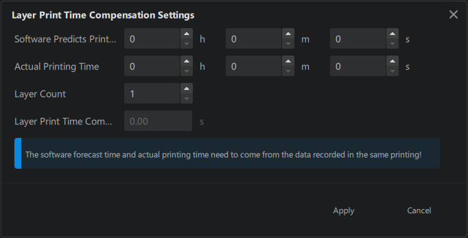
Manual Input
Layer Print Time Compensation: a 2-digit number between
-99.99and99.99with default set at0s.When enabled, the Estimated Time For A Single Layer = Exposure Time + Waiting Time + Movement Time + Layer Print Time Compensation
-
Auto Generation
Mask
Mask is designed to solve a common light source issue of uneven light strength at different spots of the screen. The issue is usually caused by improper light sources. The purpose of the mask is to provide a correction layer on the screen by adjusting the transmittance on different areas of the screen respectively, making the uneven light homogeneous.
Mask File: You can select an existing image by clicking the ... icon, or click the gear icon to create a new one using CHITUBOX's built-in mask generator.
Gray Scale Unit: click here to learn more about gray scale unit.
Mask Generator
Mask Generator in CHITUBOX supports two modes: Hub-and-Spoke and Matrix Mode。
Hub-and-Spoke
Hub-and-Spoke generate a ripple-like pattern. The number of circles is set by Number of equal parts. Radius of circles are arithmetic sequence with a delta set by Equal radius.
The range of Gray Parameter is between 0 (black) to 255 (white)。
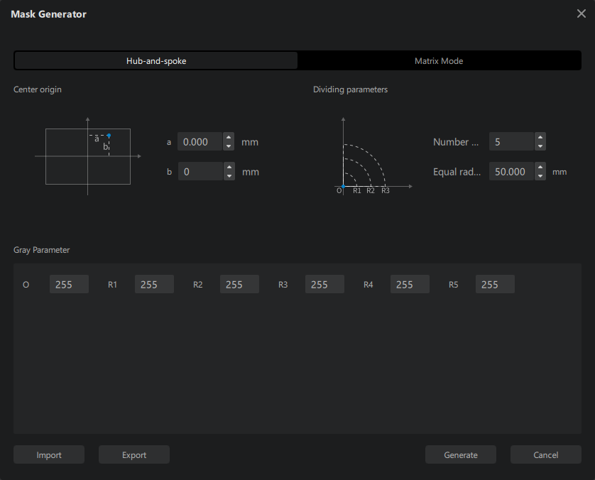
For example, if Number of equal parts is set to 5, Equal radius is set to 3mm, the radius of the ripple will be
Here is a comparison for different Equal radius:
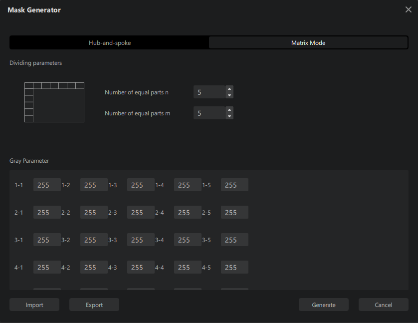
Matrix Mode
Matrix Mode generates a matrix-like pattern. Rows and columns are set by m and n respectively.
The range of Gray Parameter is from 0 (black) to 255 (white)。
For example, here is a 2 × 3 matrix with different grayscales.
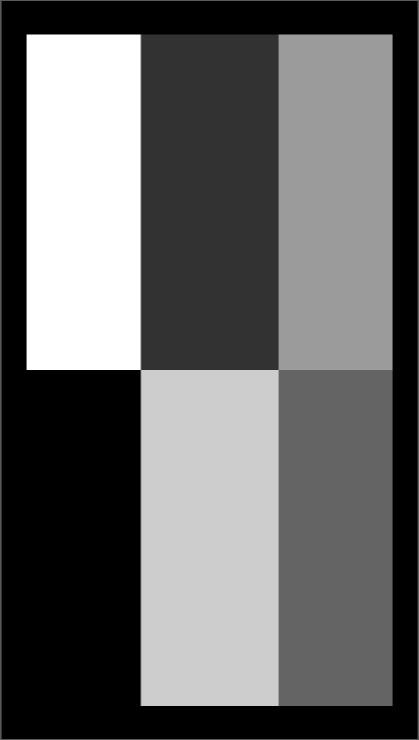
Gray scale unit
Gray scale unit is used to average the gray value of specified number of pixels in X-axis direction, and apply averaged grayscale to pixels in corresponding position of the original image.
Example:
Let's say the size of the build plate is 80mm × 120mm, the resolution of the screen is 800px × 1200px.
This is the mask picture, also with resolution of 800px × 1200px. All squares in the picture have the size of 50px × 50px.

If the Gray scale unit was set to 51px, the processed image will be like this:
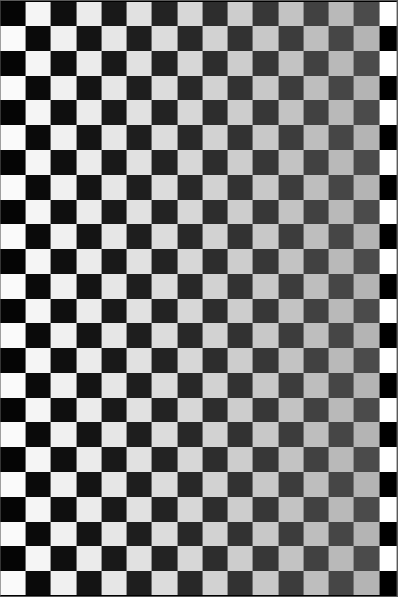
The grayscale increases from left to right as a result of averaging out every 51 pixels. Take the first row as an example: The first 51 pixels include 50 black pixels and 1 white pixel. The resulting average value is a tint lighter than pure black, barely noticeable to the naked eyes. The second group of 51 pixels contains 49 white pixels and 2 black pixels, averaging out to a color slightly darker than white. The third group of 51 pixels will be masked to the average grayscale of 48 dark pixels and 3 white pixels and so on, until we reach the remaining 35 odd pixels.
, remainder 35
This remaining pixels' gray scale will be the average of 35 pixels of the same shade. Therefore, the resulting grayscale doesn't change.