Configure Print Parameters
To configurate your print parameters, you need to add a printer first, if you have not added a printer yet, click here to see how to add a printer.
One printer can have multiple profiles, you can manage your profiles in the Slicing Profile Panel, where you can add, edit, delete, reset, import and export your profiles.
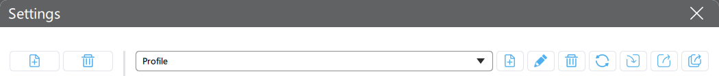
Click Settings to open the slice profile configuration window.
Settings
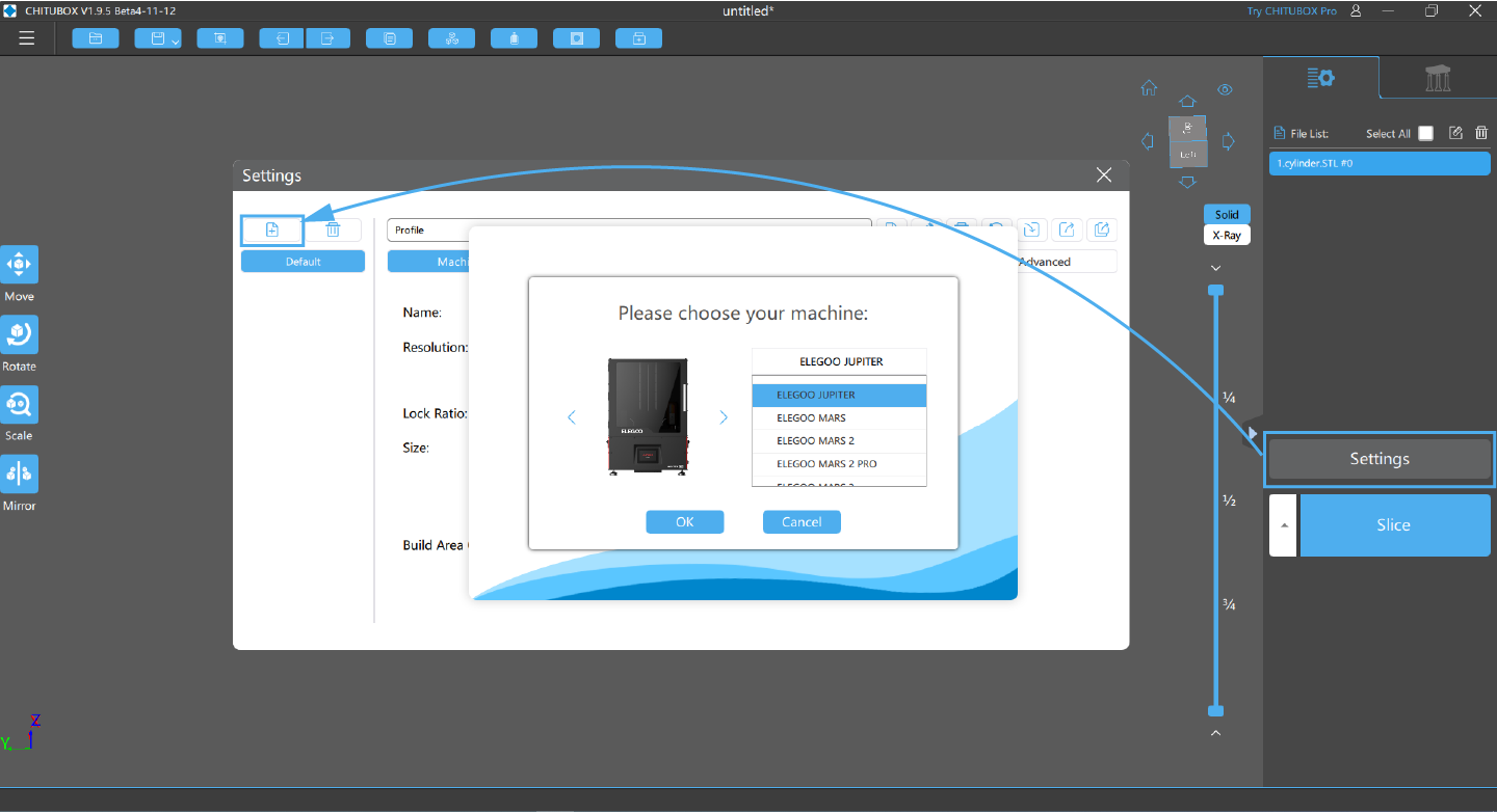
Add New Printer
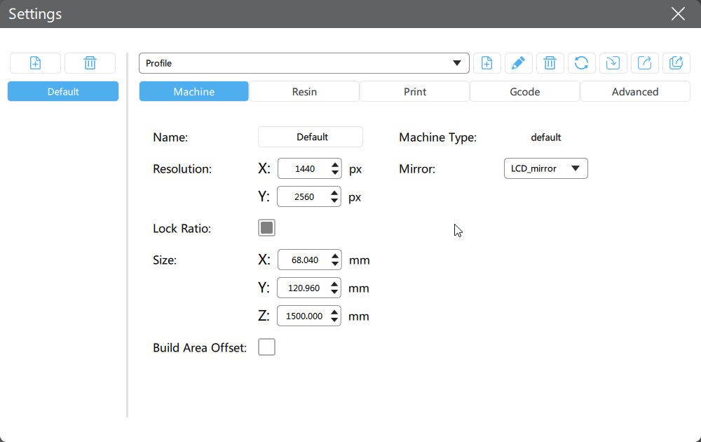
Machine
Add the configuration parameter information of the selected device.
Click 📃here to learn more about Mirror.
Build Area Offset is designed to cure the situation that there are dead pixels on the edge of the screen or the edge of the screen is used as a non-working area. Setting the offset can avoid the dead pixels.
Resin
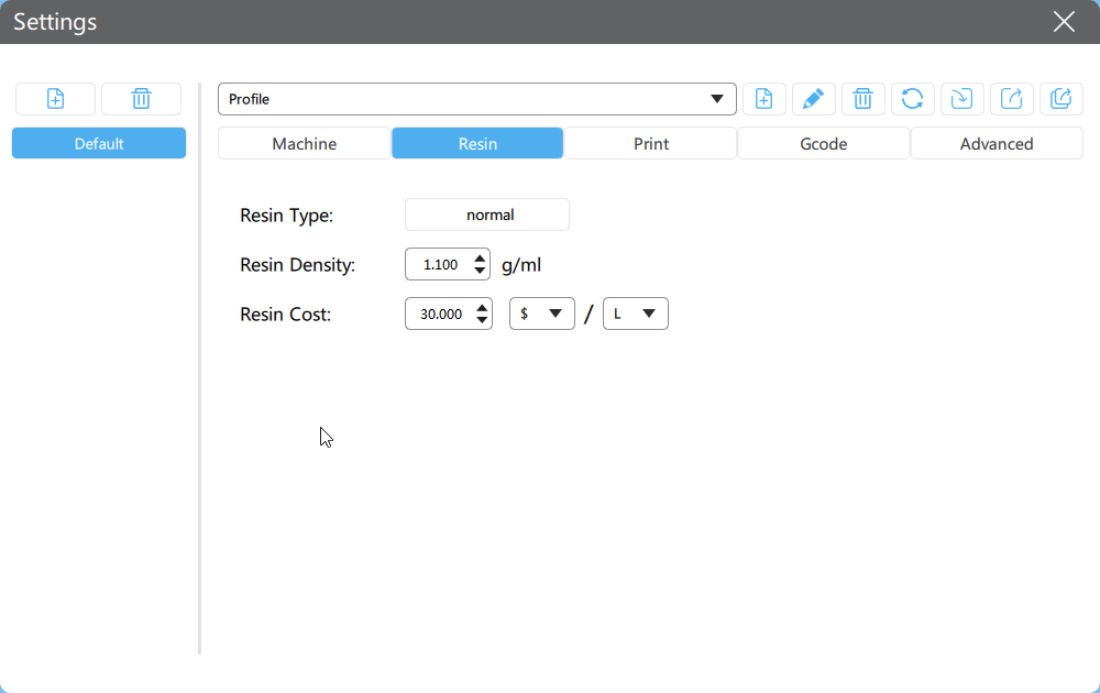
Set your resin type, density, and cost here.
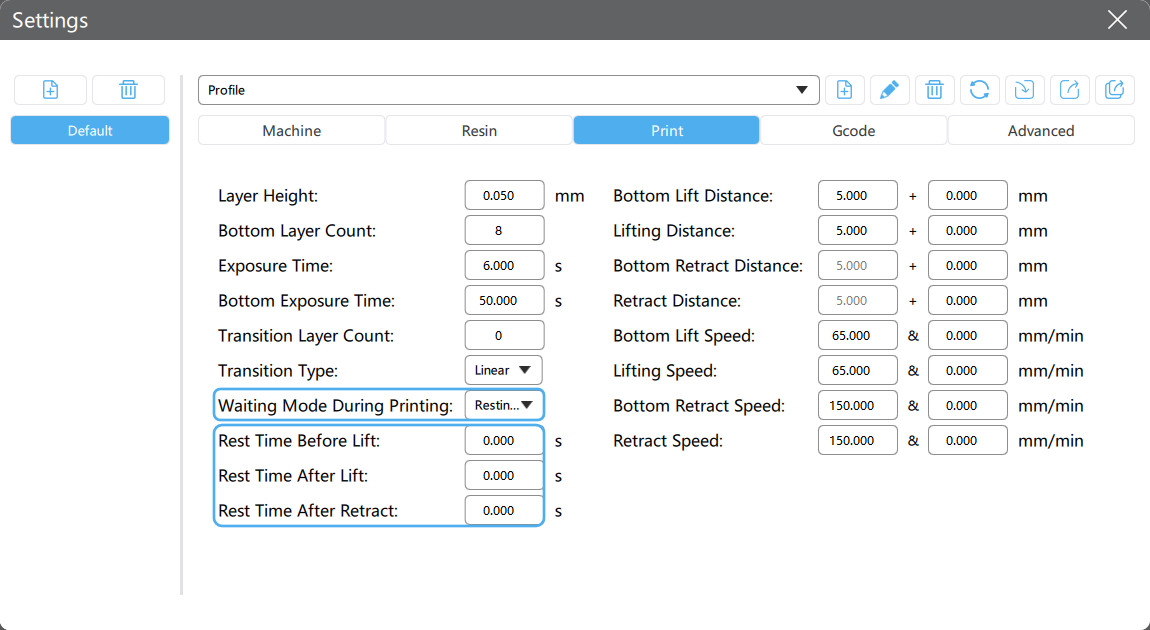
Print
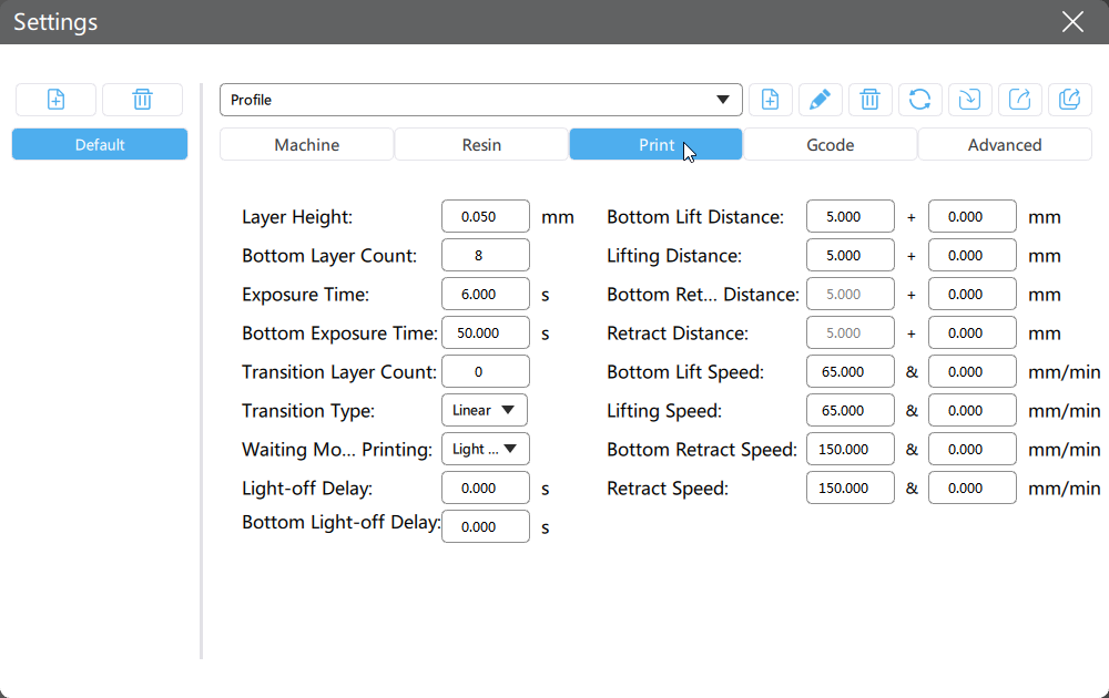
Set your printing parameters here.
Not all printers support Resting Time waiting mode. Read the 📃full compatibility list here.
1 TSMC
Not all printers support TSMC. Read the 📃full compatibility list here.
In order to shorten the printing time and ensure a higher printing success rate, CHITUBOX divides the original constant speed into two speed segments, a.k.a TSMC (Two-Stage Motion Control). When the printing platform is moving away from the printing face, it is allowed to move at a relatively faster speed.
Traditionally, there are only 2 sub-stages for a single motion cycle, after TSMC was introduced, we now have 4 sub-stages for a single motion cycle:
When both normal layers and bottom layers are involved, it makes sense that there are 8 pairs of parameters, which are highlighted in the table below:
All data in the table is only used for the explanation, please adjust the data as per your needs.
| Sub-stage | Relevant Parameters |
|---|---|
| Bottom layers slow lift | 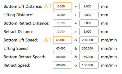 |
| Bottom layers fast lift | 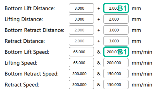 |
| Bottom layers fast retract | 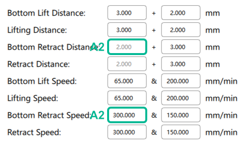 |
| Bottom layers slow retract | 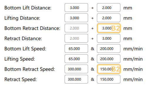 |
| Normal layers slow lift | 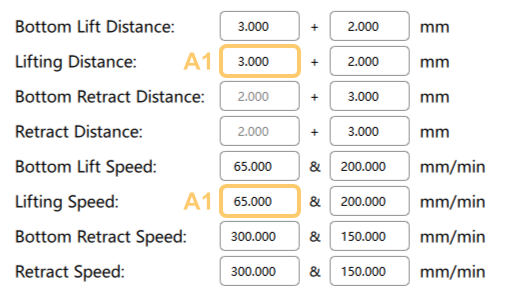 |
| Normal layers fast lift | 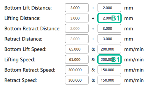 |
| Normal layers fast retract | 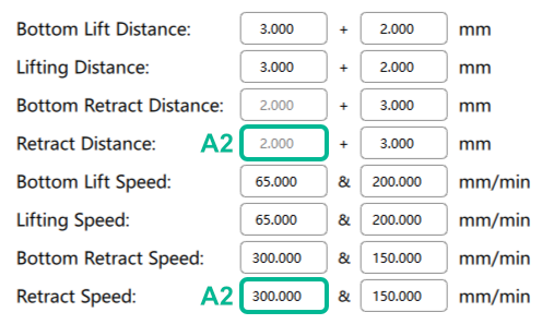 |
| Normal layers slow retract | 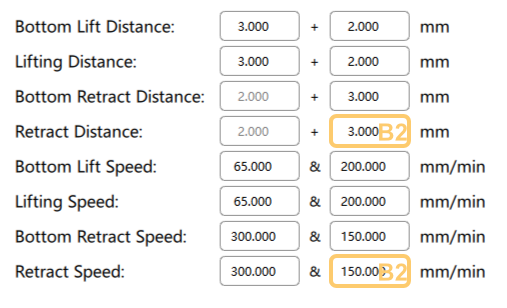 |
Please note that each Distance has its corresponding Speed, for example,
Bottom Lift Distance corresponds to Bottom Lift Speed, you can't
have a non-zero Distance with a Speed of 0, vice versa.
If you hope to stay in Legacy Motion Control, you can keep the second column
all-zero, which will remove B1 and B2. You might found that the
motion control doesn't work as per the parameter you set sometimes, this may
be caused by the limitation of the maximum speed in factory parameter.
Please contact the printer's manufacturer for details.
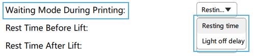
2 Waiting Mode During Printing
2.1 Resting Time
In order to simplify the calculation of Light Off Delay, CHITUBOX launched a new Waiting Mode During Printing, Resting Time, when using this mode, you simply need to fill in Rest Time Before Lift, Rest Time After Lift, Rest Time After Retract without tedious calculations.
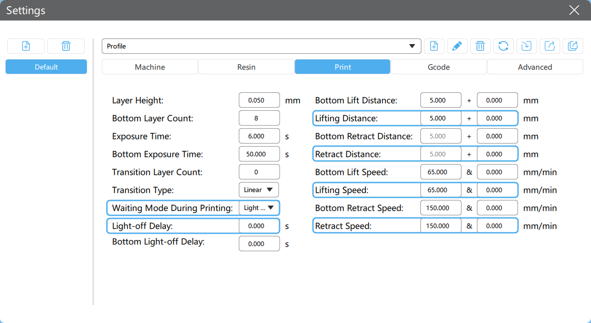
2.2 Light Off Delay
2.2.1 What is Light-off Delay?
Light-off delay is the total time of build plate lifts up, wait, and retract during resin 3D printing of one layer.
It's vital for the resin to has sufficient time to be stabilized before the printer starts the process of printing the next layer Mostly, the longer time you set for the light-off delay, the better, sharper, and higher resolution printing results you got. But if you set the light-off delay too long, the printing process gonna take you all day.
The time for lift up and retract can be various, depend on the distance of lift up, while the wait does not, we recommended it for 2~3 seconds.
2.2.2 Light-off Delay Calculation in CHITUBOX
To calculate the light-off delay, you will need to know lifting distance, lifting speed, and retract speed first. After figure out the total time for lifting and retracting, add additional 2~3 seconds of wait time, you got the light-off delay.
Light-off delay = Time for lifting + Time for retracting + Wait time
An example is worth a thousand words:
Here the Lifting Distance is 7mm, Lifting Speed is 70mm/min (1.167mm/sec), So the lifting time is:
seconds
Similarly, the Retract Speed is 210mm/min (3.5mm/sec), the retracting time is:
seconds
If we hope the minimum wait time is longer than 2s, the light-off delay should:
seconds
If you put a number less than to the Light-off Delay, it will not work.
2.2.3 Light-off Delay Calculator
Modify editable fields to get Light-off Delay.


Gcode
Don't edit anything here if you don't know what you're doing.
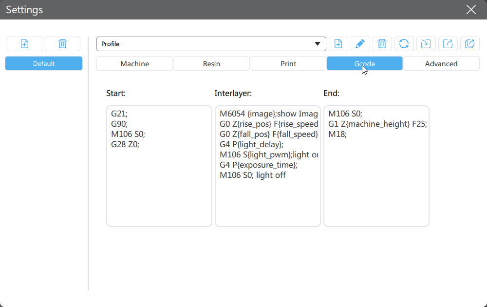
Only .zip and its derived formats (ex. .cws) support Gcode editing.
Advanced
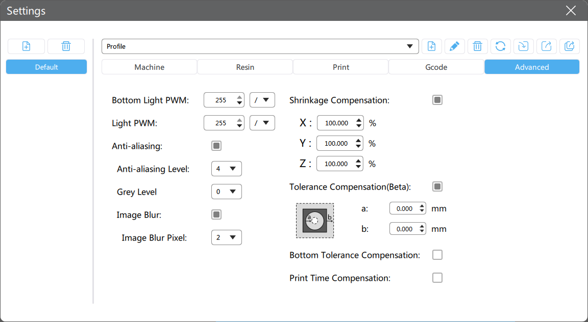
1. Bottom Light PWM
Light PWM for bottom layers, from 0 to 255 , controls the power of the UV light source for bottom layers.
Click here to learn more information about PWM.
2. Light PWM
Light PWM for normal layers, from 0 to 255 , controls the power of the UV light source.
3. Anti-aliasing
The triangular sawtooth of image edge is softened to achieve smoother surface effect. The continuity of edge exposure and the intensity of light transmission can be adjusted by adding or deleting pixel units with certain gray levels between adjacent triangular serrations, so as to achieve a smoother edge area.
-
Anti-aliasing Level :
2,4,8, designed for .cbddlp format. It determines the edge exposure time. The higher the level you select, the longer the exposure time will be, this will result in sharper edges, thereby decreasing the effect of anti-aliasing. -
Gray Level :
0~8, designed for .ctb format. It determines the number of Grayscales that can be used for anti-aliasing. The Grayscales of0~255(0represents black,255represents white) is divided into 8 levels. The higher the level, the fewer grayscales can be used and the range is closer to255(white). -
Image Blur : Enable/Disable image blur, designed for .ctb format.
- Image Blur Pixel :
2~8, determines the number of pixels for edge transition, the higher level you select, the softer edge would be. Similar to the feather function in Photoshop.
- Image Blur Pixel :
Open 📺this video and 📃this article to learn more about Anti-aliasing, Grayscale, and Image Blur.
4. Shrinkage Compensation
Shrinkage compensation of the model in X, Y, and Z directions. The percentage represents the size compared to the original size, the default value is 100%.
When the percentage value is larger, the model body is larger.
When the percentage value is smaller, the model body is smaller.
5. Tolerance Compensation
Inner and outer diameter compensation of normal printing layers.
When a is larger, the inner diameter is shorter, and the model body is larger.
When a is smaller, the inner diameter is longer, and the model body is smaller.
When b is larger, the outer diameter is longer, and the model body is larger.
When b is smaller, the outer diameter is shorter, and the model body is smaller.
Open 📺this video and 📃this article to learn more about Tolerance Compensation.
6. Bottom Tolerance Compensation
Inner and outer diameter compensation of bottom printing layers.
When a is larger, the inner diameter is shorter, and the model body is larger.
When a is smaller, the inner diameter is longer, and the model body is smaller.
When b is larger, the outer diameter is longer, and the model body is larger.
When b is smaller, the outer diameter is shorter, and the model body is smaller.
When the bottom layer tolerance compensation is disabled, the normal layer tolerance compensation will be effective for the whole model.
7. Print Time Compensation
Some high-resolution printers could have extra delays when loading data and will lead to inaccurate printing time estimation, you can set up a time compensation to improve the issue.
-
Manual Input
Layer Print Time Compensation: a 2-digit number between
-99.99and99.99, default0s.When enabled, the Estimated Time for A Single Layer = Exposure Time + Waiting Time + Movement Time + Layer Print Time Compensation
-
Auto Generated
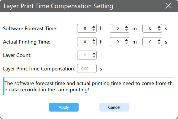
Layer Print Time Compensation =
Remember to click Apply after changing parameters, otherwise, the parameters won't take effect.