Configure Print Parameters
Before setting the print parameters, add a new printer by clicking the add button on the machine management bar located at the bottom of the main window. Choose a printer brand to expand the available printers, and then select the printer you want to add. Click the Next button to add the printer.
You can then configure print parameters for the added printer. One printer can have multiple profiles, which you can manage in the Profile Panel.
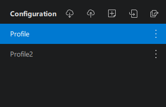
In the Profile Panel you can download profiles (from RMA or custom library), upload all profiles (to custom library), add a profile, import profiles (from local), export all profiles (to local).
By hovering each configuration's menu icon , you can see the available operations for the configuration, including upload, rename, export, reset, delete.
Machine
Here you can configure the printer's basic information, including the printer's name, machine resolution, dimensions, etc.
Name
The printer's name, editable, printer model type by default.
Type
The model of the printer, not editable.
Mirror
Exposure image mirror mode. You do not need to change this setting in most circumstances unless you are using the default printer type (Other > default).
Resolution and Size
The resolution and size of the print screen. You do not need to change this setting in most circumstances unless you are using the default printer type (Other > default).
The Link/Unlink buttons allow you to link/unlink the size and resolution or X and Y. Any linked value will be updated automatically when the other value is changed.
If dimensions are not linked to the resolution (resolution stays unchanged), the smaller the screen size, the larger the actual print will be, and vice versa.
The resolution must match the actual resolution of the printer, otherwise the printer might report an error.
Build Area Offset
The offset of the build area. Enabling this option allows the adjustment of the offset to the edge of the print screen. Offset areas will not print. This option can be used to avoid bad points on the edge.
Resin
Here you can configure data for the resin you are using, including the resin's name, type, density, unit price, etc. CHITUBOX will use this information to calculate the resin usage and cost.
Print
Not all printers support Resting Time waiting mode. Read the 📃full compatibility list here.
TSMC (Two-Stage Motion Control)
There are two sets of lifting and retracting parameters in the print settings, where you can set up TSMC.
When the build plate starts lifting with the model, the FEP film at the bottom of the resin vat will pull down the newly solidified layer until it is detached from the layer. This is called the "suction effect". The suction effect is more prominent when the contact area with the FEP film is large and when the build plate pulls away at higher speeds. The suction effect can cause the model to deform, and even cause the model to fall off the build plate. We recommend keeping the lifting speed slow until the model is detached from the FEP film. As the suction effect is no longer a concern, speeding up the lifting speed afterwards can improve the printing efficiency. The principle acts similarly in the retracting stage.
You can adjust the following parameters below to get familiar with TSMC.
GCode
Do not edit anything here if you don't know what you're doing.
Only .zip and its derived formats (ex. .cws) support Gcode editing.
Advance Settings
Bottom Light PWM
Light PWM for bottom layers, ranging from 0 to 255 or from 0% to 100%, controls the power of the UV light source for bottom layers.
Light PWM
Light PWM for normal layers, ranging from 0 to 255 or from 0% to 100%, controls the power of the UV light source for normal layers.
Picture Grayscale
Picture Grayscale is similar to Light PWM, ranging from 0 to 255. But picture Grayscale controls the light transmittance of the LCD screen Instead of the power of the UV light source.
Anti-Aliasing
There are two anti-aliasing modes: Gray Scale Level and Anti-aliasing Level (legacy).
Gray Scale Level
This mode is designed for the .ctb format.
Anti-aliasing Level
This is the legacy mode, designed for the .cbddlp format only.
Shrinkage Compensation
Model shrinkage compensation in the X, Y, and Z directions as a percentage of the original model size. The default value is 100%.
Large percentage value results in larger model entities and vice versa.
Tolerance Compensation
Inner and outer diameter compensation of normal printing layers.
When a is larger, the inner diameter is shorter, and the model body is larger.
When a is smaller, the inner diameter is longer, and the model body is smaller.
When b is larger, the outer diameter is longer, and the model body is larger.
When b is smaller, the outer diameter is shorter, and the model body is smaller.
Bottom Tolerance Compensation
Inner and outer diameter compensation of bottom printing layers. This setting is often enabled to address the "elephant's foot" issue.
When a is larger, the inner diameter is shorter, and the model body is larger.
When a is smaller, the inner diameter is longer, and the model body is smaller.
When b is larger, the outer diameter is longer, and the model body is larger.
When b is smaller, the outer diameter is shorter, and the model body is smaller.
- When the bottom layer tolerance compensation is disabled, the normal layer tolerance compensation will be effective for the whole model.
- Bottom Tolerance Compensation only applies to bottom layers. Enabling both layer transition and Bottom Tolerance compensation can lead to unexpected printing results.
Set Transition Layer Only
Enabled Bottom Tolerance Compensation Only
Enabled Both Transition Layer And Bottom Tolerance Compensation
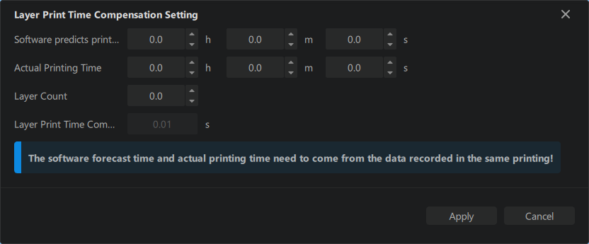
Print Time Compensation
Some high-resolution printers can have extra delays when loading data and will lead to inaccurate printing time estimation. You can set up a time compensation to improve the issue.
-
Manual Input Layer Print Time Compensation: a 2-digit number between
-99.99and99.99, with default set at0s. When enabled, the Estimated Time For A Single Layer = Exposure Time + Waiting Time + Movement Time + Layer Print Time Compensation -
Auto Generation